We encourage you to verify the source images for yourself, rather than just simply accept the facts that are presented here.
Exact details of the used image templates can be found here.
Some reports on this website are based on previous ones. So it is extremely important to read the reports in chronological order.
Details can turn up that were probably already been analyzed in detail. If you are new here and you directly start reading the
recent reports without prior knowledge, then it could happen that the required context is not recognizable.
You do yourself and us a favor when you first start with the oldest reports.
This is the first analysis report on this structural anomaly in Arabia Terra. There are no previous reports. You can continue to read here.
Target Area
The recording, which was made from the no longer active Mars Global Surveyor space probe, displays an area that is located
northeast from Arabia Terra.
Click on image to enlarge
With about 1.78 meters per pixel it is one of those recordings of the MGS probe that were created with a relatively
high resolution. The MOC camera onboard the Mars Global Surveyor space probe was theoretically able to create images
with a resolution up to 1.5 meters per pixel, but this was only possible under optimal conditions.
Below is a table overview of the metadata, which show that the image was taken with a small tilt perspective and it
was not perfectly perpendicular shot to the surface.
The official metadata of the recording
The image with the ID "M0304371" is the only one of the MGS probe, which maps the structure.
Focus on the structural anomaly
Apart from Mars Global Surveyor, the CTX camera aboard the Mars Reconnaissance Orbiter has captured the appropriate area
with a much lower resolution. The same structure is still visible here. Also this image serves as an important reference
image for further analysis.
First Reconstruction Attempt
It has been more than a year, when the MAP team had registered a striking structure on the present MOC image.
With so many eye-catching structural anomalies that have been discovered, this recording did not got any more
attention and was stored in an appropriate archive for later detailed image analysis.
Subsequent to the development of other methods for rapid detection and breakdown of structural characteristics
this record reappeared upon review of the archive. Unlike many other structural abnormalities that
were discovered within the analysis project, this example shows particular properties, which represent
long anticipated structures. There is here a high degree of symmetry and exact geometric characteristics.
The approach for the breakdown of this anomaly is described in detail below.
One of the important note-giving methods is the detection of symmetry properties within an object.
It should necessarily be noted that this method initially only serves to identify worthwhile candidates
that could be considered as artificially created structures. This is not a method that should be used
as a means of evidence for artificial objects.
The criticism of such practices is absolutely justified. A flood of such examples can be found in many
video portals that contain clips with references to seemingly symmetrical objects. But rarely can these examples
withstand an exact performed test. Weakness of these mostly freehand conducted symmetry checks are errors
in the logic of the image perspective that are willfully be overlooked or recklessly forced symmetries in which
various bumps in the Martian landscape are randomly chosen as reference points.
Such kind of symmetry check can only serve as a first hint. Based on this, further methods must be used,
which in reverse may explain why some features are to be seen on an image exactly as they are seen. The more
precise and consistent these results are, the more likely a structual anomaly can be seen as artificial object.
A first reconstruction attempt shows the following freehand created concept sequence in an animation.
Animation - Click on the image to enlarge
On the lower resolution recording of the CTX camera fine details inside this formation can not be recognized,
however the recording of the MOC camera reveals more details, that exhibits characteristics of
a square looking structure. Also this detail should be detained.
Animation: Highlighting of strutural features within the anomaly
The impression that is formed here based on the reconstructed lines is that of a symmetrically
structured construction. The lower part exhibit characteristics that could be interpreted as an
entrance area. This impression is reinforced by an unusually bright spot that is located exactly
to the central of the symmetrically designed entrance area. But precisely this area was supposed
to be completely in the shade like the rest of the environment. How this striking bright spot
comes about, can not be obviously explained. It is also remarkable and unusual for a natural geological
formation that in turn the upper part shows centrally located a kind of deepening with (incomplete)
square-like features.
One point of criticism that may be list here, is that not all lines are clearly visible. The
continuation of some outlines in the shown reconstruction sequence could also be judged negatively
as arbitrariness. The circumstance that these lines follow a logical continuation based on clearly
recognizable outlines, can not and should not completely refute this criticism.
Therefore it is necessary to keep this criticism in mind and to see if there are further hints
that are able to refute such doubts.
At this point, we have just some striking features. It still seems obvious that this structure can be
described as a natural geological formation (butte/mesa). Even for us the collected abnormalities so
far are not yet sufficient to eliminate doubts. It is mandatory to find more clues which have a
strong explanatory power.
Evidence of Precise Geometry
A high degree of symmetry is a first good indication of specific structural anomalies. However, do the
reconstructed outlines fit well according to the logic of the image perspective?
By drawing longitudinal and transverse axes along this structure, the following particularities can be observed:
1. The start and end points of the width axis, are marked by the two tapered corners to the left and
the right side of the structure. The line which is drawn through these points passes the inner chamber.
The line traverses the chamber not at any point, but precisely at those points where the lines
of the inner chamber visibly end respectively begin.
2. If we mark as start and end point for the longitudinal axis the tapered edge at the upper
end of the structure and the bright spot in the lower part of the postulated entrance area,
then the corresponding line will also passes through the inner chamber in exactly two vertices.
For a freehand drawn model these similarities are located remarkably precise.
Animation - Click on image to enlarge
It should be noted that the line reconstruction appears initially asymmetrical on the MGS image.
In fact, this apparent "slant" is absolutely logical for a symmetrical object, as the
recording was taken with a certain perspective tilt. The logic of the perspective, which show the marked
outline, remains consistent.
In addition to the shown symmetries there are surprisingly regular distance relationships mutually visible,
when we draw further guide lines. These include, for example, the two long side lines, which run parallel
to the entrance area. At the points at which these side lines end/start, it is possible to draw in turn another
horizontal line, which also run parallel to the first drawn horizontal line. Furthermore it is possible
to draw diagonal lines that exactly cut the distance of the upper two tapering outlines in the half at
right angles. The intersection points where the diagonal lines cut the outlines form the vertices of a
regular quadrangle.
Apart from the plurality of symmetrical and geometric coincidences, there is also a further
amazing coincidence to mention. The structural anomaly is closely aligned with the east-west axis of Mars.
This can be easily verified with the help of the Google Earth application in the Mars view mode.
The here attached image shows the structure based on the CTX camera that is part of the Mars
Reconnaissance Orbiter probe.
Original cut - North-oriented CTX Mosaic Orientation to the cardinal points
Reconstruction Based on a Derivable Geometry
The outline and guide lines drawings show some inaccuracies, which is not surprising for freehand drawn lines.
If it corresponds to the facts that the whole structure is constructed exactly symmetrically and
also follows geometrically derivable rules, it must therefore be possible, to construct a model, which
underlies the rules of this Mars structure and which later can be displayed accurately on the
original image. To test this assumption, it is now necessary to work as precisely as possible.
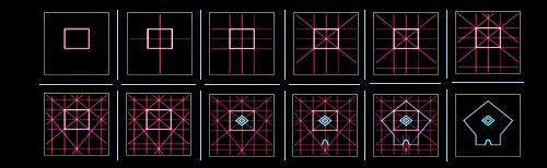
Let us take a look at the last image of the reconstruction sequence:
Derivable geometric rules recognizable on the reconstruction plans
There are various description possibilities, with which the present outlines can be defined based on geometric
relationships, but the end result should finally always look the same.
Following rules can be used for the creation of an own template:
Click one of the image segments for further details
The image below illustrates the exact reproduction of the previously derived geometric rules:
A template with the exact reproduction of the derived geometric rules
Pattern Matching with the 2D Template
Since the image of the Mars Global Surveyor spacecraft has not been taken in an exact right angle (check meta-data)
to the surface of Mars, but with a slight tilt, the completed template must be accordingly tilted in its perspective.
Click on image to enlarge
The pattern matching between the original image and the template shows an accurate compliance with the traits
of outline features in the original photo.
Animation: Pattern Matching
The created template itself is symmetric up to the core. The positions are firmly defined. Each attempt of
explanation can now be carried out on a fixed unalterable template and can always be cross-checked with the
original image. Both images must be consistent with each other, otherwise the made assumptions about the
geometry/symmetry are wrong.
There remain important points to clarify now. For example: The lines of the presumed square-like inner
chamber are exactly there where they should be on the original image, but why is just a part of this inner
structure visible? There are also some other inconsistencies. Could it be a misinterpretation or is possible
to give verifiable explanation?
The templates that was used here can be downloaded (without perspective inclination) in different versions
(as JPG image files) within a zip package:
File object_2d_templates.zip
Size 227 KB
Calculation of the Structure Size
The calculation of the structures sizes on the Martian surface can be considerably simplified by applications
such as Google Earth. A built-in program ruler function allows the measurement of a distance between two
markers. Based on the CTX shots that have already mapped a large part of the Martian surface, it is possible
to obtain relatively good measurement values on various Martian structures.
Focus on the structural anomaly via Google Earth
Despite the lower resolution of the CTX images, clear and concise outline features of the present Mars
structure can be identified. To obtain a reference value, it makes sense to choose the two vertices in the
reconstruction which represent the width of the Mars structure, since these boundary points are clearly
visible on the CTX recording.
The ruler feature of Google Earth in use
The ruler function shows here for the predetermined distance a value of almost exactly 200 meters.
For such measurements, of course one have to allow for some tolerances, but the value is not expected
to move much away of these 200 meters. The circumstance that almost exactly 200 meters were measured,
we simply take out as a practical fact. Because due to the fact that there is a pattern that follows
geometrically derived rules, it is possible to derive all other size values with this one reference size.
The derived values based on the geometric characteristics of the template
Accordingly, with the width of 200 meters now a total length of 250 meters can be derived. The side
length of the outer square in the center must therefore be 50 meters and 25 meters for the inner square.
So far, this structure was an abstract entity, but now with the present size information it is possible to
gain a sense of the spatial dimensions. So far, this structure was an abstract entity, but now with the
present size information it is possible to gain a sense of the spatial dimensions.
At this point it makes sense to perform a cross-check. According to the derivations the total side length
of the back part of the building, at the entrance area, must equal 100 Meters. Cross-checking is ideal here
because even on the CTX image this area emerges clearly visible.
The ruler feature of Google Earth in use cross-check - Rear side length
With about 99 meters, the measured result is consistent with the value derived from the template. It is always
important to use the opportunity for cross-checks to find and to prevent possible errors and inconsistencies.
Creation of a 3D Model
The compliance with the template that was created according to the specifications of geometric regularities
is already amazing enough, however, this is just the beginning. Upon closer examination of the of the probe image it
is noticeable that the inner chamber only shows part of a applied square space. According to our template a completely
square structure should be located here. It would be easy to explain this circumstance by weathering, as well as sand
and dust drifts, which have covered the interior part. One can see quite clearly how the sand piles up around the edges
of this "plant". But considering the fact that just a two-dimensional template has served here for the pattern matching,
it is probably due the lack of spatial vision that those conditions can not be shown and demonstrating what somebody would
see, if he looks at a real three-dimensional object with the same perspective tilt. The inability of a 2D template to
represent real dimensionality also explains the fact why the innermost square cavity is inconsistent with the template
within the pattern matching.
Focus on the "inner chamber" - Comparison with the template Slight deviation of the inner square
The outer square shape however is on a level/plane with the rest of the other outlines, which is consequently also in the
balance with the original image. It is easy to recognize that the dark square shapes have a certain thickness.
An indication that a step-like depression is present here. On a purely 2D template without additional spatial information,
it would not be possible to map such details.
In order to present a further possibility, which may serve as evidence of the artificiality of this object, it is
absolutely necessary to create a three-dimensional model, which is also subject to exactly the same geometric rules.
A for this purpose created 3D model (in a wireframe view) was superimposed over the original photo to show the
compliance with the outline and the inner chamber.
Click on image to enlarge
The 3D model reveals an astonishing detail. Oriented approximately in the same perspective, the model shows just
the half the edges of the interior. They are not visible. Exactly as it is shown to the original image. The viewing angle
contributes that the rear inside walls stay hidden and thus for the viewer, or for the probe, virtually no edges can
be detected. Consequently this is a natural and verifiable visual effect.
The 3D model without texture in the same perspective
The following image area allows direct interactive control of the constructed 3D model. The model can be set congruent
with the structure on the original MOC camera image.
Keep left mouse button pressed to rotate Simultaneously press the shift button to zoom
Interactive 3D model - Click on image to control the model
The comparison with the inner chamber can now demonstrate that the spatial representation of the
model and the original MOC image can be placed exactly over each other. Actually, it can be illustrated
very accurately that the present features can be entirely explained by a step-like depression. This
involves the elimination of the lower edges, which extend to the corners of the square inner area,
while only the upper half can be seen with its the darker inner walls.
Focus on the "inner chamber" - Crossfade with the 3D model Exact compliance with the step-shaped depressions
The images can solve the inconsistency that had arisen with the 2D template. The outer lines of the central chamber
was correctly placed, however the inner lines were slightly misplaced. The 3D model can now give a verifable explaination.
The 2D template wasn't able to depict spatial depth
on a plane. Other aspects are likewise dissolved. The bright spot in the presumed entrance area was outside of the 2D template,
but the 3D model can show, that it is placed on a side of the walls, where it makes a logical sense. We can additionally
emulate the effect of the sunlight on the model and can explain the dark areas on the original image. These are shadow areas.
The example used in this 3D model is provided as a download in OBJ format:
File 3d_model.obj
Size 18 KB
For the presentation of the model a 3D graphics application
(such as "Blender " or
"Obj Model Viewer ")
is required that supports the used standard format.
Conclusion
It is possible to set an absolutely symmetrical model that was constructed by geometrically derivable
rules congruent on this strucure anomaly. Based on the MOC image of the Mars Global Surveyor probe and
the CTX image of the Mars Reconnaissance Orbiter probe, it is also possible to derive more than a dozen
reference points that correspond, in case of the MOC image, the logic of the image perspective. Moreover,
this formation is accurately aligned to the cardinal points.
The reconstructed 3D model points to a building that has very catchy features that allow, among other
things, the allocation of the entrance area. The visible internal square-scale chamber has probably been
designed from the outset, to be clearly visible. The function of this building, can not be determined at
the moment.
But if it turns out that this type of building with its distinctive can also be found shape on Earth,
then this could lead to very interesting conclusions. An extensive search for this model shape appears
to be very useful and can possibly resolve the question of its function.
At this point, we must become aware of how many coincidences are actually necessary in order to describe
these structural anomaly as a rock formation that is created due to natural geological processes.
An attempt with different methods of image analysis was made to show evidence of artificial influence.
The 3D models can, in turn, explain why certain edges and lines are not visible on the MOC image and can
also give conclusive evidence of the construction of this structure anomaly. None of the previously
discovered anomalies has such highly symmetric and geometric features, as in this case. There are other
remarkable details, which must be addressed in a further analysis report.
It is instructive to look at the circumstances that have contributed to the finding of this structural
anomaly. Although the image analysis can show many precise symmetries, this structure is initially
completely inconspicuous. Google Earth offers seven global map views for the examination of the Martian surface,
but none of these views would have, in the least, give the impression that there is something special
here. Groundbreaking, however, was a high-resolution recording of the Mars Global Surveyor probe, from
the series of so-called "Narrow Angle Images" and not one of the images of the global Mars maps.
The narrow angle images of the MOC camera maped only a very small part of the planet's surface and are of
varying quality. Since sveral anomalies hunters try to discover conspicuous structures only by free walking
through the Martian surface with the help of applications like Google Earth, this method is of limited success.
The majority overlook a crucial point. If there were clear evidence of artificial structures, they would have
already found this ten years ago by one of the many anomaly hunters in the internet respectively the
appropriate supervisory authorities would had "defused" this information effectively before publishing them.
The approach by using the global Mars map for anomalies can therefore provide only limited useful results.
Focus on the structural anomaly
Results of the various views of the seven global Mars maps
There are only two options (Visible Imagery and CTX Mosaic) in the selection of the global Mars maps
that are suitable for an area analysis with reasonably good resolution. These are, as this case shows,
unusable for finding striking structures because it is not possible here to reproduce fine structures
and thus to recognize specific details. So these maps are just helpful in the subsequent analysis to
find more insightful information and to get an impression of the surrounding area. Without "real"
high-resolution images the efficient detection of structural anomalies remain mostly accidental
discoveries, if we are forced to use only the Visible Imagery/CTX Mosaic Mars map options.
This leads to the last crucial point:
Artificial structures can appear directly in front of us, without recognizing it. This is mainly due
to the clever distribution of high- and low-resolution images that are made available. Already at a
resolution beyond about 3 to 4 meters per pixel, even large structures can merge with the environment
beyond recognition.
Global Mars maps (as those based on CTX Mosaics) suggest that Mars was depicted almost completely in a
supposedly high resolution. But this resolution is far too small to identify any artificial structures.
Under these conditions the structures must have extremely huge proportions in order to be recognized.
Even high-resolution images such as "m030437", which has a resolution of about 1.7 meters per pixel is
not noticeable at first glance. The slightly inclined angle is enough to shift spatial perspectives,
and to make the recognition of symmetric properties very difficult. In addition, sand and dust drifts can
cover the outlines of such a structure, and thus the possibilities for finding artificial structues
disappear almost entirely.